7/14/17
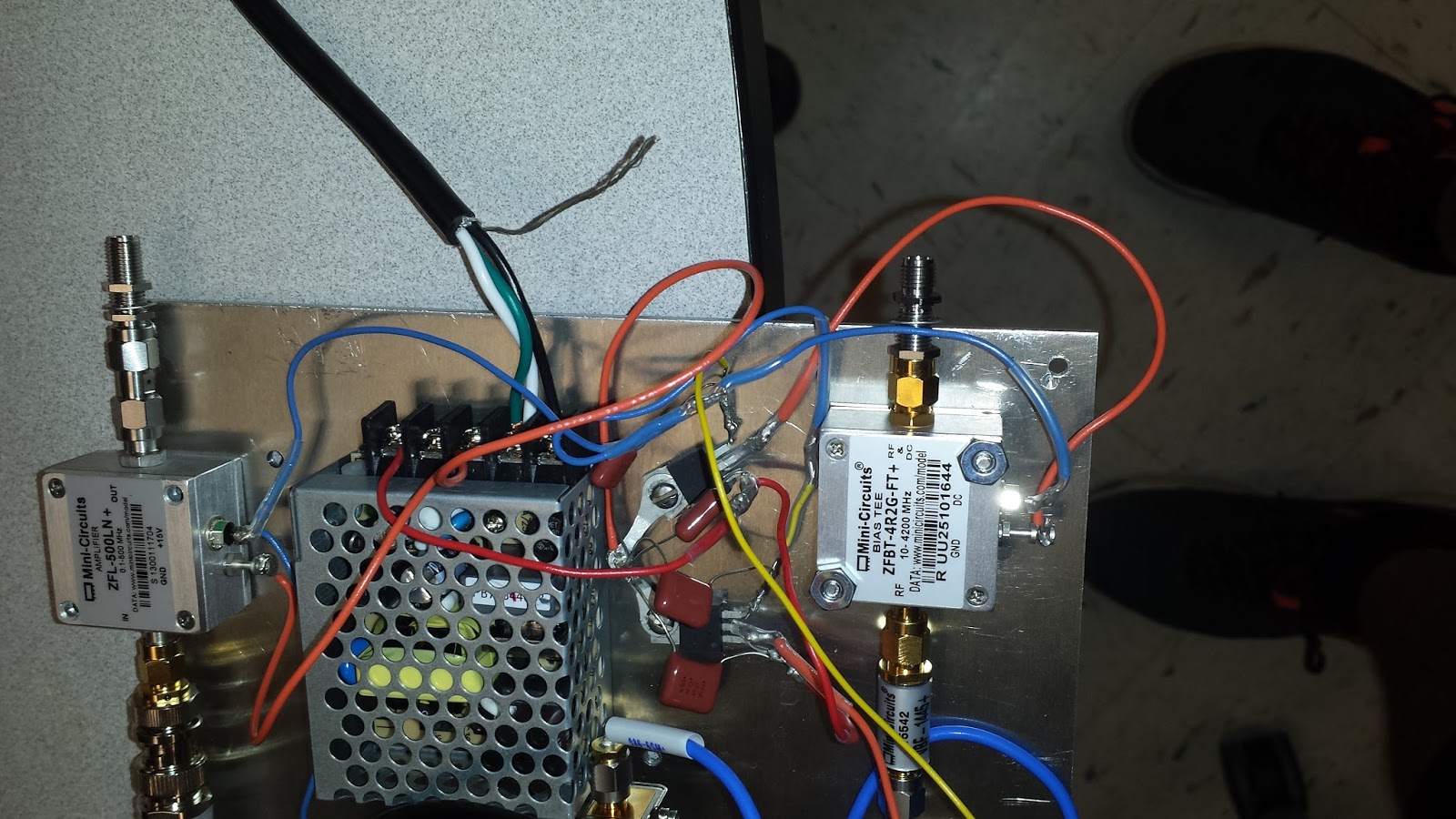
The final working simulink code and function within is shown above. In conjunction with PRMS (Pasco Rotary Motion Sensor) we are able to tell what angle the Viper Radio telescope is pointed at...
Some important notes:
-DO NOT have anything uploaded to your arduino or have anything open that could block simulink from connecting to the port.
-DO NOT locate which serial port you are using by looking at the Arduino IDE... it may be wrong... instead enter 'cd /dev/ ' into the terminal, then type 'ls', then remove your usb, then type 'ls' again to see which one from the list is there when you have the usb plugged in and not there when the usb is unplugged. Should be located below the bluetooth stuff. Enter this into Host-board connection port number for a proper connection. It was '/dev/tty.usb.modem1411' for me.
-The sample time inside the two digital input pins is set to 0.0001. If we go to 0.00001 simulink will be too slow to be anywhere near accurate. However, 0.0001 is still too small of a sampling time to get a perfect reading, but it is the best we can do for right now... a sampling time of 0.000025 is the eventual goal. Uncertain if this is a simulink limitation or a limitation of the computer I am using.
-You must set the serial 0 baud rate to 115200 inside of this menu shown below... click the gear looking icon at the top of simulink to get there.


 we managed to install the second wheel today as well as the outside face of the center wheel on top of getting the wheels set in the right place


